Guide 01 / Mechanical system
Flex Meets Geometry
Follow the load from the point through the blade, tang and grip. The useful question is not simply “How stiff is it?” but “What does this construction do under a defined load?”
- Section and taper
- Heat treatment
- Tang and assembly
Start with the section, not the label
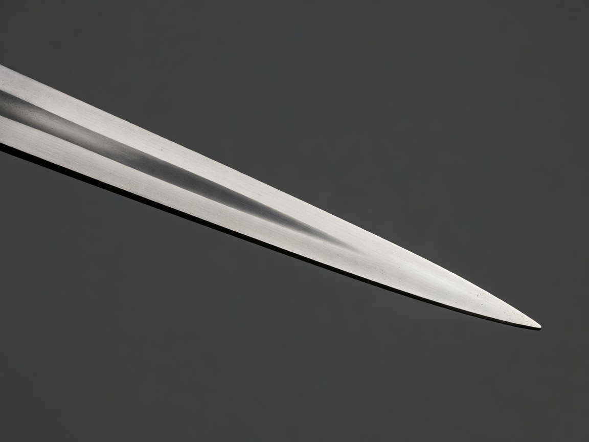
A fencing blade is a tapered elastic member, not a uniform spring. The section changes along its length, and the orientation of that section affects resistance to bending. In elementary beam terms, bending stiffness combines the material's elastic modulus with the second moment of area. That relationship explains why a modest geometric change can have a noticeable effect even when the steel grade remains unchanged.
A foil blade, an épée blade and a sabre blade do not share an interchangeable mechanical brief. Their sections, points and intended contact behaviour differ. Before comparing two specimens, identify the weapon, the measurement direction, the support arrangement and the point of load application. A free-hand bend is a useful observation for an experienced armourer, but it is not a controlled stiffness measurement.
Published dimensions and flexibility procedures belong to the applicable FIE Material Rules. Read the current document rather than transferring a limit from another weapon or an old checklist. Our explanation of section mechanics is engineering interpretation; it does not replace the prescribed inspection geometry.
Separate material choice from processing
“Steel” is only the beginning of a specification. Alloy composition, processing route, heat treatment, surface condition and residual stress all influence the finished component. Maraging steel is associated with high-performance fencing blades, but a material designation alone does not prove the quality or service history of an individual blade. Traceability and the relevant approval requirements still matter.
Manufacturing can introduce both useful properties and local vulnerabilities. A groove, a sharp transition or a surface defect may raise local stress. Changes near the tang are especially important because the assembly transfers hand loads and bending moments through a relatively compact region. A polished appearance does not demonstrate the absence of internal defects, and a hardness measurement does not independently establish fatigue resistance.
General methods such as ISO 6892-1 for tensile testing and ISO 6507-1 for Vickers hardness can help characterise material behaviour in a properly designed programme. They are not substitutes for weapon-specific requirements. Sampling location, specimen preparation and heat-treatment condition must be recorded; otherwise a technically correct measurement may describe a coupon that is not representative of the finished blade.
Treat the hilt as a load path
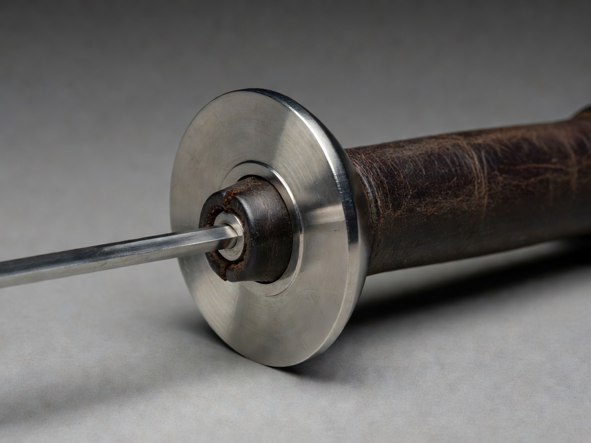
The guard, insulating components, grip and retaining fastener determine how the blade is supported in use. A loose joint can change feel, allow relative movement and disturb an electrical connection. Excessive tightening can also create problems. Follow the component manufacturer's assembly instructions rather than applying an arbitrary torque or adding a locking compound whose compatibility is unknown.
Inspect seating surfaces and verify that the assembly is compatible before interpreting a change in handling as a blade defect. Record the grip type and any adjustment to the assembly during a comparison. If one blade is tested in a different hilt, differences in boundary conditions can obscure what the blade itself contributes. Controlled comparisons keep these supporting parts constant wherever practical.
Read fatigue evidence cautiously
Fatigue concerns damage accumulated under repeated loading. A blade can behave normally in a simple elastic check while carrying a developing defect. A permanent set, unusual local kink, visible crack, corrosion pit or unexplained change in response warrants removal from use and assessment under the manufacturer's guidance. Do not attempt a workshop repair intended to conceal damage or force a suspect blade back into service.
A fatigue comparison needs more than a count of bends. State the load or displacement range, bending direction, frequency, support geometry, environment and failure criterion. Record how many specimens were tested and whether they came from the same batch. Results from one specimen are a case observation, not a reliable estimate of an entire product population.
Finally, distinguish survival in a bench sequence from safety in every fencing encounter. Real use includes variable impacts, torsion, assembly changes and environmental exposure. The responsible conclusion is narrow: this identified specimen produced this result under this method. Combine that evidence with current rules, manufacturer instructions and routine inspection rather than turning a single result into a universal service-life claim.