Guide 02 / Electrical system
Where the Signal Travels
A scoring indication is the output of a connected system. Understand the intended circuit before using a meter to decide which part is wrong.
- Point switch
- Insulation
- Connectors
- Apparatus
Begin with the weapon's logic
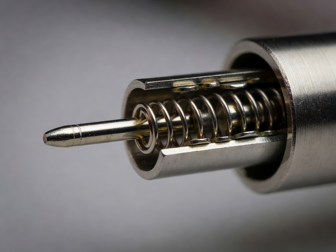
Foil and épée points are both mechanical assemblies, but their electrical logic differs. In the conventional wired foil system, the resting point circuit is closed and point depression opens it. In épée, point depression closes a contact between the two point wires. These descriptions are starting models, not complete explanations of how an apparatus recognises a valid hit.
Sabre does not use a spring-loaded point switch to register a touch. Conductive contact between the weapon and the opponent's conductive target is central to its electrical detection. Across all three weapons, target connections, grounding arrangements, timing rules and apparatus behaviour affect the final indication. A continuity buzzer cannot reproduce all those decisions.
Use the current FIE Material Rules and Technical Rules to identify the relevant arrangement. Do not assume that a connector pin has the same purpose merely because two plugs appear similar. Establish the actual pin mapping from reliable equipment documentation before connecting an instrument.
Follow each interface
The signal path crosses several interfaces: point contacts, blade wiring, the weapon socket, body wire, reel or alternative connection system, piste-side cable and apparatus. Conductive clothing and mask connections add their own interfaces where required. Every separable contact is a potential location for contamination, wear, looseness or an intermittent connection.
Mechanical and electrical functions overlap. Strain relief prevents repeated cable movement from concentrating at a termination. Insulation keeps conductors apart and prevents unwanted contact with the weapon's metalwork. A component may show continuity while its insulation has failed, or show adequate insulation while a conductor is broken. Those are different faults and need different checks.
For a useful inspection, isolate the component from powered apparatus and follow the manufacturer's testing instructions. Inspect before measuring. A displaced connector, damaged jacket or visibly loose termination can explain a symptom without speculative changes to several components. Never probe mains-powered scoring equipment internally unless you are appropriately qualified and working under a suitable safety procedure.
Make a reading mean something
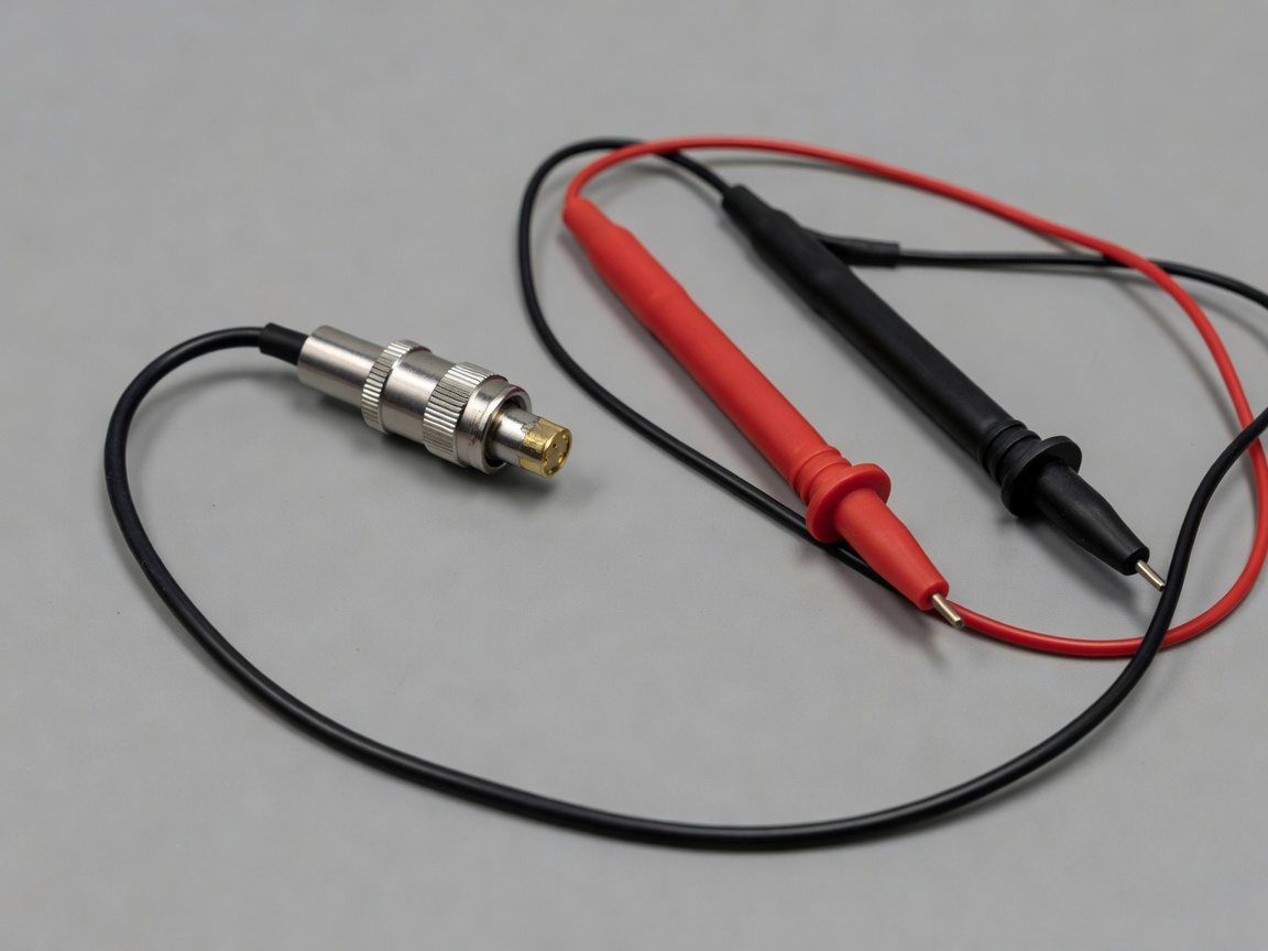
A resistance measurement includes the test setup as well as the component. Lead resistance, contact pressure, dirty probe surfaces and instrument resolution matter when the quantity of interest is small. Check the leads, note the instrument range and use an appropriate method before comparing a reading with a specified limit. A displayed zero is not evidence of exactly zero resistance.
A stationary test can miss a cable that opens when bent. Under a safe, unpowered test arrangement, observe the reading while gently moving the cable near normal flex points and connectors. Avoid aggressive bending that creates a new defect. Record which movement reproduced the fault, rather than writing only “wire bad”.
The IEC 60512 series provides general connector test methods, but that does not make every method necessary or appropriate for a fencing body wire. Select a method for the actual question and distinguish an engineering investigation from a competition equipment check.
Isolate faults without losing the evidence
Start with a reproducible symptom: which weapon, which apparatus, what movement and what indication? Then substitute one known-good component at a time. If the symptom disappears after replacing both the weapon and the body wire, the experiment has not isolated either one. Restore the original arrangement where safe and narrow the comparison.
A “known-good” component needs a recent basis for that description. It should have been checked in an appropriate setup, not simply taken from a different bag. Keep a small record of substitution order and results. This prevents circular troubleshooting, especially when more than one worn component is present.
Point travel, contact behaviour and apparatus timing also require methods beyond a simple resistance check. Use the relevant approved tools and current procedures for competition inspection. Do not alter a scoring apparatus, defeat grounding arrangements or modify a point to produce a convenient bench indication. A successful light on the box is not proof that the equipment meets all requirements.
After maintenance, repeat the original symptom check and the applicable inspection sequence. Record the replaced part and any adjustment. If the result remains intermittent, stop treating the repair as complete. The objective is a stable, explainable system response, not a single favourable reading captured between failures.